
ES130-261 Site Planning: PV Input, Distribution and Battery Cabinets
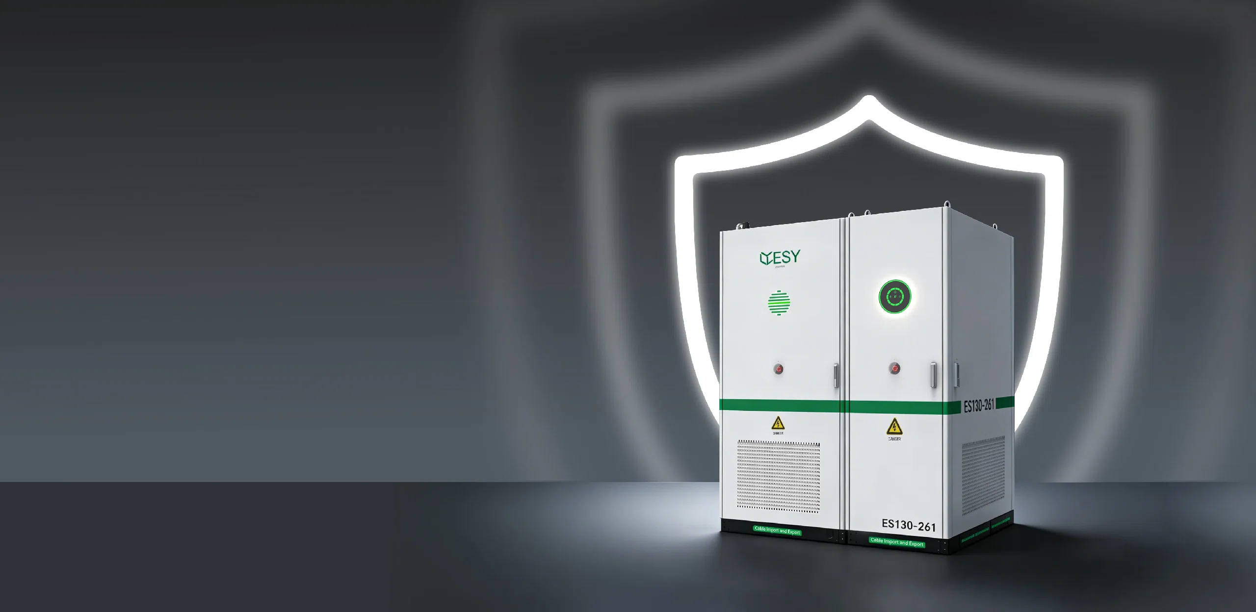
A well-planned ES130-261 site layout integrates PV input, power distribution, and battery cabinets to improve electrical efficiency, safety, and maintenance access. A typical 261kWh storage system requires accurate cabinet positioning, optimized cable routes, and thermal control. With proper planning, DC cable length can be reduced by 15–30%, while battery temperature differences can be maintained within 5°C for more stable long-term operation.
PV input, distribution, and battery cabinet arrangement determine how efficiently an ES130-261 system operates after installation. A commercial hybrid ESS must coordinate solar generation, battery storage, and grid interaction within a limited installation area. In projects completed after 2020, many commercial energy storage systems have adopted modular cabinet designs because they simplify transportation, installation, and future capacity expansion.
The site layout should allow short electrical paths, safe maintenance space, and stable environmental conditions. A well-arranged system reduces unnecessary cable length and improves installation quality.
PV input planning starts with understanding the photovoltaic array configuration, DC voltage range, current capacity, and connection distance. The PV side usually includes string inputs, protection devices, disconnect equipment, and monitoring connections. For a 130kW-class system, multiple PV strings may need to be combined before entering the power conversion stage.
The distance between PV input cabinets and conversion equipment directly affects energy loss. Copper cable resistance increases with cable length, causing additional voltage drop during high-current operation. For example, reducing a DC cable route from 80 meters to 40 meters can lower cable losses by approximately 1–2%, depending on cable size and operating current.
A practical PV cabinet layout should consider:
| Item | Recommended Planning Consideration |
|---|---|
| DC cable distance | Keep routes as short as possible |
| Cable separation | Separate power and communication cables |
| Expansion space | Reserve additional connection capacity |
| Protection access | Allow inspection without moving equipment |
The PV input arrangement also affects future system upgrades. Many commercial facilities increase solar capacity after the first installation period. A reserved cabinet area and additional cable pathways can reduce modification work when new PV strings are added in later years.
After PV energy enters the system, power distribution cabinets manage the connection between the energy storage unit, local electrical loads, and the grid. Distribution equipment normally includes AC breakers, protection relays, metering devices, and communication modules.
The distribution cabinet position should maintain a clear electrical flow from energy conversion equipment to the grid connection point. In installations where cable routes exceed 50 meters, additional material costs and installation time can increase noticeably. Shorter AC pathways also reduce voltage losses during peak discharge periods.
A balanced distribution layout separates high-current equipment from communication components, helping maintain stable operation and easier maintenance.
The ES130-261 system can be integrated into commercial facilities requiring peak load management, renewable energy use, and backup power capability. The product configuration can include PV input, storage batteries, and diesel hybrid functions depending on project requirements. More details about this type of system configuration are available through the commercial hybrid ESS solution.
Battery cabinet placement requires additional planning because lithium-ion batteries are sensitive to temperature, airflow, and installation conditions. Most LFP battery systems operate within approximately 15–35°C for normal performance. When battery temperature differences between modules increase, charging efficiency and aging consistency may decline.
A battery cabinet layout should include:
-
Front access space for inspection and maintenance
-
Airflow channels between cabinets
-
Protection from direct sunlight and moisture
-
Suitable clearance for emergency response equipment
Temperature management has a measurable influence on battery lifetime. Studies published between 2018 and 2024 show that continuous operation above 40°C can accelerate capacity reduction compared with operation near 25°C. Maintaining temperature differences below 5°C between battery modules helps keep cell performance more consistent during long-term cycling.
The relationship between cabinet spacing and thermal performance requires careful evaluation. Cabinets installed too closely may restrict airflow, while excessive spacing increases land use and cable length. Engineering design usually balances cooling requirements with available installation space.
A typical ES130-261 outdoor arrangement may follow this structure:
| Equipment | Main Function | Layout Priority |
|---|---|---|
| PV input cabinet | Receives solar DC power | Close to PV cable entry |
| Battery cabinets | Store electrical energy | Good airflow and service access |
| Distribution cabinet | Connects AC output | Near grid connection point |
Cable management connects all cabinet planning decisions together. DC cables, AC cables, grounding conductors, and communication lines should follow separate routing paths. Poor cable organization increases installation difficulty and may create maintenance issues during system inspection.
For high-power energy storage systems, cable trays and protective conduits should be designed according to current capacity and environmental conditions. In commercial installations completed in 2023 and 2024, modular cable routing methods have become common because they reduce installation time and support easier equipment replacement.
A clear cable pathway improves inspection efficiency and reduces the chance of connection problems during long-term operation.
Safety planning must also be included during the initial site design. Battery energy storage systems contain large amounts of stored electricity, requiring protection against overcurrent, overheating, insulation problems, and abnormal operating conditions.
Cabinet spacing, grounding design, fire protection equipment, and monitoring systems should be considered together. International standards such as NFPA 855 and IEC 62933 provide guidance for energy storage installation safety and system arrangement.
Communication design is another part of ES130-261 planning. Modern energy storage systems use battery management systems (BMS), energy management systems (EMS), and remote monitoring platforms to collect operating information. Communication cables should avoid close contact with high-current power cables to reduce electromagnetic interference.
A complete site planning process usually includes:
-
Reviewing available installation space and environmental conditions.
-
Confirming PV input capacity and cable routing requirements.
-
Selecting battery cabinet positions based on cooling and access needs.
-
Arranging distribution equipment according to grid connection conditions.
-
Checking safety clearance, grounding, and communication pathways.
The final arrangement should provide reliable electrical performance while allowing maintenance teams to inspect and service equipment efficiently. A well-designed ES130-261 installation can reduce cable losses, improve thermal consistency, and support stable operation throughout the expected service period.